Introduction to Technical Embroidery
Table of Contents
Section outline
-
Technical embroidery is reshaping the future of textiles—combining the precision of automation with the creativity of engineering to craft flexible, functional fabrics for an astonishing range of industries. Unlike traditional additive manufacturing methods, which often focus on rigid parts, technical embroidery enables the creation of dynamic, complex structures directly on flexible substrates, offering unparalleled design freedom.
Today, many products once manufactured through 3D printing, hand assembly, or molding are being reimagined through technical embroidery—resulting in faster production, reduced labor costs, and breakthrough innovations in fabric functionality. Highly automated, scalable, and versatile, technical embroidery opens doors to possibilities that conventional manufacturing methods simply cannot match.
And this is just the beginning.
As a rapidly evolving technology, technical embroidery is continuously expanding into new markets and applications. Major innovations are already taking hold in sectors such as:
-
Composite manufacturing (carbon fiber and hybrid reinforcements)
-
Smart textiles (heating elements, sensors, and actuation)
-
Fiber optic placement (for communication and sensing)
-
Flexible electronics (circuits and wearable tech)
Driven by automation and the low cost of scaling production, technical embroidery is not just enhancing existing textile applications—it's fundamentally transforming how entire industries think about materials, design, and manufacturing.
Welcome to the Frontier.
At ZSK Academy, we invite you to explore the future with us. Whether you're developing a new product line, seeking innovative production methods, or just starting to dream big, technical embroidery offers the tools and technology to bring your ideas to life faster—and better—than ever before.
In this guide, you'll discover:
✔ The Business Advantages of integrating technical embroidery with ZSK’s cutting-edge solutions
✔ Key Components of a ZSK Technical Embroidery Machine—and why they matter
✔ Material Innovations: from traditional threads to conductive fibers, carbon fibers, and optical strands
✔ Technical Embroidery Techniques: Explore core methods like tailored fiber placement (TFP), zig-zag functional stitching, and automated thread laying—and where each technique shines
✔ ZSK Automation: Unleash the full power of automation options for ultra-fast, precision manufacturing
✔ Your Next Steps: How to connect with us and start exploring your own products, lines, or custom ideas with technical embroideryThe future of flexible, functional manufacturing is already here. Let’s create it together.
-
Students mustMark as done4.8 MB · Uploaded 6/01/21, 20:10
-
-
In technical embroidery, embroidery heads are the heart of the machine. Each embroidery head is an individual embroidery station equipped with its own set of needles, attachments, and functional components, capable of producing designs independently. These heads are where the magic happens—where thread, wire, fiber optics, and advanced materials are precisely laid down to create everything from decorative patterns to highly engineered functional textiles.
Each head operates as a dedicated workstation, executing a specific design or sequence according to the programmed instructions. Depending on the type of head and its setup, it can stitch traditional thread, lay down technical fibers, insert functional components, or even build multi-material assemblies directly onto a base fabric or substrate.
What is a Multi-Head Embroidery Machine?
When multiple heads are combined into a single machine frame, you get a multi-head embroidery machine. In multi-head systems, several embroidery stations work simultaneously, vastly increasing production capacity and efficiency.
For example:
-
A two-head machine can embroider two identical designs at once, cutting production time in half compared to a single-head machine.
-
Larger systems, like 4, 6, 8, or even 12+ heads, are common in both traditional and technical embroidery, especially when scaling up production for commercial or industrial purposes.
Multi-head machines maintain precise synchronization, ensuring uniform quality across all embroidered products. This is critical in technical applications where exact fiber placement, electrical continuity, or aerodynamic performance might depend on stitch-perfect replication across multiple parts.
W-Head Embroidery (Tailored Fiber Placement, TFP)
-
Purpose: Used for laying down continuous fibers, such as carbon fiber, fiberglass, aramid (Kevlar®), or specialized yarns.
-
How it works: The W-Head places technical fibers precisely onto a substrate using a zigzag or tailored stitch, allowing exact control over fiber orientation and density.
-
Applications:
-
Aerospace composite reinforcement
-
Automotive lightweight components
-
Sporting goods (bike frames, skis, etc.)
-
Load-bearing structures in architecture and civil engineering
-
Tailored Fiber Placement (TFP) allows structural optimization by orienting fibers exactly where forces will act, reducing material use while increasing strength.
W-Head Embroidery (Cord and Wire Laying)-
Purpose: Used for laying wires, optical fibers, tubing, and thick cords onto textiles.
-
How it works: The W-Head gently places and secures thicker or more delicate materials onto fabric without causing damage. It stitches the material into place with minimal tension or deformation.
-
Applications:
-
Smart textiles (e.g., embedding heating wires or sensors)
-
Fiber optic networks in flexible structures
-
Medical textiles (embedded tubing or flexible circuits)
-
Flexible and wearable electronics
-
The W-Head's gentle laying mechanism is critical when dealing with fragile or performance-critical materials that traditional sewing heads would break or distort.
K-Head Embroidery (Moss and Chain Stitching)
-
Purpose: Used for creating chenille embroidery moss and chain stitches
-
How it works: The K-head uses a single hooked needle to pull a loop of thread from the bottom of the machine to the top, creating a textured surface. By timing, the loop can be stand alone (forest mode or moss mode) or looped through itself creating a chain stitch.
-
Applications:
-
Smart textiles (textile electrodes)
-
Varsity jackets
-
Insulation
-
Fixation of thick threads
-
The K-Head's stitching mechanism requires no rotary hook (unique compared to other stitch types). This means there is no bobbin. For that reason, the K head can stitch longer without an operator replacing bobbins. Additionally, since the thread is a single continuous thread, there are unique mechanical and electrical applications.
F-Head Embroidery (Flatbed Embroidery and Multi-Material Stitching)-
Purpose: Used for traditional embroidery and functional stitching with finer threads or decorative/technical yarns.
-
How it works: The F-Head operates more like a high-precision flatbed sewing machine, offering high-speed stitching with complex patterning capabilities.
-
Applications:
-
Logo embroidery and branding
-
Conductive thread stitching, circuit board stitching
-
Insulation (electrical) layer stitching
-
Fabric reinforcement and assembly
-
In technical embroidery, F-Heads are often used alongside W- or K-Heads to add secondary functions—like stitching around technical fibers for durability or stitching an additional layer over functional materials.
Combining Different Head Types for Maximum Flexibility
A major advantage of ZSK’s technical embroidery platforms is their modular design, allowing multiple head types to be combined on a single machine. For example, a machine might feature a W-Head for laying carbon fiber and an F-Head for securing it with an outer stitch layer—all in one production pass.
This flexibility means you can custom tailor your manufacturing setup to the specific requirements of your application, whether you're building lightweight composite panels, smart wearable devices, or next-generation sensor fabrics.
Why it Matters
Choosing the right combination of heads isn’t just about stitching—it's about unlocking new performance, efficiency, and innovation possibilities:
✅ Precision placement of complex functional materials
✅ Ability to scale to high-throughput production
✅ Integration of multiple material types in a single manufacturing pass
✅ Reduction of material waste through smart design and tailored reinforcementAt the ZSK Research and Training Center in Seattle, we're ready to help you design, configure, and launch the embroidery solutions that will power your next-generation products.
Technical embroidery isn’t just stitching—it’s engineering. And the right embroidery heads are where it all begins.
-
-
The Pantograph: The Driving Force Behind Precision Embroidery
In any modern embroidery machine—whether traditional or technical—the pantograph plays a critical and often underappreciated role. It is the mechanical system that moves the embroidery frame in the X (left/right) and Y (forward/backward) directions, allowing intricate designs to be stitched or technical materials to be precisely placed across the surface of the backing fabric.
The pantograph ensures that the material moves beneath the stationary needle, rather than trying to move the needle itself across the work area. This strategy, born from centuries of embroidery tradition and refined by modern robotics and CNC motion control, is the key to achieving high-speed, highly accurate embroidery.
A Quick Look Back: The History of Embroidery and Machine EvolutionEmbroidery as an art form dates back thousands of years, with ancient examples found from China, Egypt, and India. Originally, embroidery was performed entirely by hand—a time-consuming and painstaking process where artisans moved the needle through a stationary fabric surface.
The modern era of embroidery machines began in the early 19th century with manually operated chain stitch machines. By the late 1800s and early 1900s, machines began to evolve, particularly in Europe (notably in Germany and Switzerland), where innovators developed mechanical solutions to automate parts of the process.
The pantograph system was introduced as a breakthrough innovation, allowing operators to guide a needle across a large work area using a mechanical tracing arm. Early pantograph embroidery machines were manually operated with large templates.
Fast forward to today: modern technical embroidery machines use computer numerical control (CNC) to move the pantograph automatically and with extreme precision, based on a digital design file. No more tracing by hand—every stitch or material placement is driven by sophisticated software and high-speed electronics.
What Exactly is the Pantograph?The pantograph is the mechanized XY table that holds the embroidery frame (which in turn holds your fabric or substrate). It physically moves the entire frame precisely according to the design path programmed into the machine's control system.
Key Functions of the Pantograph:
-
X-Axis Movement (left and right)
-
Y-Axis Movement (forward and backward)
-
Holding and tensioning the embroidery frame securely during motion
-
Coordinating with the embroidery head to ensure perfect stitch placement
Unlike what some might assume, the needles themselves do not "draw" across the fabric. Instead, the needle moves up and down vertically while the pantograph moves the material horizontally under the needle, effectively "painting" the design with thread, wire, fiber, or other technical materials.
How Does the Pantograph Move? (Motor Systems Explained)Modern pantographs are driven by high-precision motors, which are typically either:
-
Servo motors (for high-speed, high-accuracy industrial embroidery machines)
-
Stepper motors (in smaller or more cost-conscious machines)
Servo Motors:
-
Offer continuous feedback on position and speed, meaning the controller knows exactly where the frame is at all times.
-
Allow for dynamic speed adjustments mid-design, for example slowing down for complex corners and speeding up on straight paths.
-
Provide higher accuracy and smoother motion, critical for technical embroidery applications like fiber placement, heating wire layout, or flexible circuits.
Stepper Motors:
-
Move in fixed steps without feedback.
-
Are simpler and less expensive but slightly less precise at very high speeds or with highly complex designs.
In advanced technical embroidery systems like those from ZSK, industrial-grade servo motors are standard, enabling frame movements that are smooth, rapid, and synchronized perfectly with the needle cycles.
Why the Pantograph is Essential for Technical EmbroideryAcross all three major technical embroidery methods—W-Head (Tailored Fiber Placement), K-Head (Cord and Wire Laying), and F-Head (Flatbed Functional Stitching)—the pantograph remains the common foundation:
✅ In W-Head embroidery, the pantograph guides the base material while fibers are precisely stitched down along pre-programmed trajectories.
✅ In K-Head embroidery, it ensures that delicate wires, cords, or tubes are gently and accurately placed without stretching or damaging them.
✅ In F-Head embroidery, it allows detailed, complex stitching patterns to be built rapidly, layer by layer, even when multiple material types are involved.Without a reliable, high-performance pantograph, achieving precision technical embroidery would be impossible. It acts as the "invisible hand" steering the entire embroidery process from underneath.
A Note on the Naming of PantographsThe term "pantograph" originally comes from the Greek roots:
-
"panto-" meaning "all" or "every"
-
"-graph" meaning "writing" or "drawing"
In early machines, the pantograph was literally a mechanical arm that could copy drawings at different scales—thus, the same name came to be used in embroidery machinery, where designs are "drawn" onto fabric by moving the material under a stationary needle.
Today, in technical embroidery, the term honors that tradition—while the function has become far more advanced, involving CNC programs, CAD-generated designs, and real-time motion control.
In SummaryThe pantograph is the soul of motion in embroidery machines.
It moves the world underneath the needle, enabling high-speed, high-precision, and highly creative technical embroidery that is revolutionizing industries from aerospace to smart textiles.At the ZSK Academy, we train innovators not only on operating embroidery machines—but on understanding the fundamentals of pantograph design and control, so they can truly master the new frontier of textile engineering.
Move the material. Change the world.
The Pantograph holds the frame (in blue) which allows for X and Y movement on the embroidery table.
-
-
Understanding Frames and Backing Materials in Technical EmbroideryThe frame is a vital part of the embroidery machine that is moved by the pantograph across the X and Y axes to create the design. It holds and tensions the backing material, allowing the embroidery head to stitch or place technical materials precisely onto the surface.
Frame Considerations for Technical EmbroideryChoosing the correct frame size is one of the most important decisions when selecting an embroidery machine for your application. Frames can range from just a few centimeters wide—for highly specialized uses like footwear embroidery—to over one meter by one meter for large technical panels.
However, it’s important to understand that some margin of the backing material will always be consumed by the clamping mechanism. The clamps secure the material in place but create a "non-embroiderable" border around the design area. The exact width of this unembroiderable edge depends on the clamp style and the embroidery technique being used.
- W-Head embroidery (Tailored Fiber Placement) typically requires a larger margin because of the way fibers are laid down and stitched.
- K-Head and F-Head embroidery can often proceed much closer to the clamp edge, maximizing usable design space.
Clamping Methods for Holding Backing MaterialsThe backing material can be mounted onto the frame using several types of clamps, each suited for different stages of development or production needs:
- Manual Clamps: Quick and flexible, manual clamps allow fast testing across a variety of materials—different thicknesses, textures, and friction levels. Clamping force and surface properties can often be customized depending on the specific technical requirements of the project.
Showing how the frame clamps over the fabric with manual clamps below.
- Pneumatic Clamps: Ideal for production environments, pneumatic clamps automate the clamping process, improving throughput and consistency. They apply adjustable, uniform tension across the fabric and are especially valuable in high-volume manufacturing settings. Less common for rapid prototyping due to their setup requirements.
- Magnetic Clamps: Magnetic clamping systems use high-friction surfaces and magnetic forces to secure the material. They enable fast material changes, making them highly efficient for applications requiring repeated setup and teardown while maintaining excellent tension control.
Showing the stitchable area in the frame below:
What is the Backing Material?The backing material is the fabric, film, mesh, or technical substrate that is loaded into the frame. It serves as the foundation into which the embroidery—whether thread, fiber, wire, or tubing—is stitched.
Depending on the strength, flexibility, and durability of the chosen backing, additional layers called stabilizers might be required. Stabilizers reinforce the backing from below, holding stitches securely and preventing issues such as puckering, tearing, or fiber pull-out during or after embroidery.
Common Examples of Backing Materials in Technical Embroidery- Standard thermoplastic woven and nonwoven fabrics
- Glass fiber and carbon fiber woven/nonwoven fabrics
- Plastic films (such as PET or TPU films)
- Tarping and outdoor performance materials
- Biomedical substrates (biocompatible or disposable materials)
- Natural materials like leather, silk, and organic textiles
- Metallic wire meshes for conductive or shielding applications
- Decorative laces with structural support
- Soft and semi-rigid foams for cushioning and flexible architecture
Visual ExamplesShowing the thickness of the frame. Thicker frames clamp the fabric better, however you'll lose embroidery area.
-
The T8 Controller: The Brain of the Embroidery MachineIn the embroidery process, digital design files are loaded into the machine’s controller—known as the T8 Control Terminal—either via a network connection or by inserting a USB drive.
Before embroidery begins, the operator uses the T8’s built-in touchscreen to review the loaded design. They can check the layout, set design parameters, adjust stitch start points, and confirm that everything is correct before initiating production.
How the T8 Communicates with the MachineOnce embroidery is started, the pantograph and embroidery heads no longer act independently—they continuously receive real-time commands from the T8.
The T8 sends highly detailed instructions to the embroidery machine’s internal computer systems, which in turn direct the servo motors that drive the pantograph’s X and Y movement.
Key functions coordinated by the T8 during embroidery include:
- Precise control of frame movement (X and Y axes)
- Timing and synchronization of needle up/down motion
- Adaptive speed control based on the geometry of the design
- Real-time compensation for inertia changes caused by different frame or material weights
This means that simple, straight-line running stitches can be executed at very high speeds, while complex corners, tight curves, or fine details automatically trigger the machine to slow down for maximum precision—all without requiring any manual intervention.
The T8 is Like the CNC Controller of EmbroideryIn many ways, the T8 Control Terminal functions similarly to a modern CNC (Computer Numerical Control) machine interface.
Just like a CNC machine reads a toolpath file (such as a G-code program) and converts it into movements of motors and mechanical components, the T8 reads an embroidery design file (typically in .DST, .DSB, or similar formats) and orchestrates every motion needed to execute it perfectly.
Instead of moving a milling head or laser nozzle, the T8 moves:
- The embroidery frame (through pantograph control)
- The embroidery needle (up and down with precise timing)
- Specialty attachments (like cutting devices, fiber placers, or cording modules)
The T8 is not just a storage unit—it's a live, intelligent system actively managing motion, timing, material interaction, and feedback throughout the embroidery process.
Why Firmware Updates MatterBecause the T8 is a sophisticated control computer, its performance depends heavily on its internal software—known as firmware.
Manufacturers like ZSK continuously improve firmware to:
- Optimize speed and precision for new embroidery techniques
- Fix minor bugs or compatibility issues with new design file types
- Improve user interface features and workflows
- Enhance motor control algorithms for even smoother, faster embroidery
- Introduce support for new attachments and expanded capabilities
Therefore, it is highly recommended to keep your T8 firmware updated regularly. Updating firmware ensures your machine runs at peak efficiency, reduces the risk of system errors, and unlocks the latest features developed for technical embroidery innovation.
At ZSK Academy, we train all users on how to properly update and maintain their T8 units, helping you keep your embroidery operation at the cutting edge of performance.
Summary: The Nerve Center of PrecisionThe T8 Controller is the nerve center of every ZSK technical embroidery machine. It is the critical interface between your digital design and the physical movement of the embroidery process.
Understanding and maintaining your T8 is not just a matter of convenience—it’s essential for achieving the highest levels of precision, efficiency, and innovation in technical embroidery.
Smart designs need a smart controller—and the T8 delivers.
-
History of Machine Stitching – Precursors to Embroidery
Machine stitching began with the invention of the lockstitch sewing machine in the early 19th century, most notably patented by Elias Howe in 1846 and commercialized by Isaac Singer. These early machines used a reciprocating needle and a rotary shuttle hook to interlock a top and bottom thread, forming a stitch. The primary application was garment assembly, but the precision and repeatability of the stitch laid the foundation for automated embroidery.
Embroidery-capable machines evolved from these foundations by adapting the feed system to allow multi-directional movement of the fabric or hoop rather than linear feed motion. By the mid-20th century, pantograph-controlled machines could trace a pattern, and later CNC-style servo control allowed computer-guided decorative stitching.
Above, showing an image of a traditional stitching head (F-Head)
Core Mechanisms of Machine Stitching
At the heart of most stitching machines is the lockstitch mechanism, formed by the interplay of:
- A needle carrying the upper thread
- A rotary hook (or oscillating shuttle) that loops around the needle to catch and pull the thread
- A bobbin holding the bottom thread
- A needle bar driving vertical movement of the needle
- A feed mechanism (in sewing) or pantograph/hoop movement system (in embroidery) to control fabric position
The thread take-up lever pulls slack thread after the stitch is formed, ensuring correct tension and preventing tangling.
Stitching Threads
There are a wide variety of different threads that work throughout the embroidery process as both upper and lower threads. These variations open many different material possibilities and technical capabilities. Thread quality including technical parameters such as twist per inch, denier, stock material, and lubrication factors are all important in the embroidery process and required to achieve optimal speeds and results.
Threads not designed specifically for embroidery can cause numerous thread breaks and other machine problems. It is recommended to use high-quality embroidery-grade thread. Standard embroidery grade is usually 40 weight; finer applications use 60wt, 75wt, or even 120wt thread.
Limitations
- Extremely elastic materials (like spandex) may cause skipped stitches
- Coarse or abrasive materials (e.g., fiberglass) can prematurely wear down needles and thread paths
- Heavy materials require higher torque and specialized needles; thin or sheer materials may pucker if tension is not properly tuned
What Has (and Hasn’t) Changed
Still the same
- The needle, needle bar, rotary hook, and thread take-up lever remain largely unchanged in function
- The lockstitch remains the foundational stitch in most machines, including commercial embroidery systems
What’s changed
- Servo and stepper motors now drive precise movement of hoops or frames
- Digital controls and CNC programming allow for image-based stitch design and automatic color changes
- Sensor feedback systems monitor thread breakage, hoop position, and thread usage in real-time
Mechanical Systems: Inside the Embroidery HeadKey mechanical components that coordinate motion and stitch formation include:
- Thread Take-Up Lever: Pulls back excess thread after each stitch
- Reciprocator: Drives vertical motion of the needle bar
- Rotary Hook: Spins around the bobbin to catch and lock the top thread
- Bobbin Case and Tension Spring: Holds and tensions the lower thread
- Catcher: Helps clear threads or trims in automatic trimming systems
- Trimmer Mechanism: Cuts threads at color changes or design end-points
- Jump Mechanism: Lifts the needle and shifts position without stitching
- Color Change Actuator: Moves the correct needle into position for multi-color embroidery
These components are synchronized via a combination of cams, timing belts, and digital controllers to maintain millisecond-level timing accuracy.
How a Needle and Rotary Hook Form a Lockstitch
1. Needle descends
The needle, carrying the upper thread, moves downward through the fabric. As it pierces the fabric and reaches its lowest point, the thread is pushed through, creating a loop just above the eye of the needle.
2. Rotary hook catches the loop
As the needle begins its upward motion, the rotary hook begins to spin. The hook's sharp point is precisely timed to intersect with the loop of thread formed behind the ascending needle, catching and pulling it around the bobbin case.
3. Loop is pulled around the bobbin thread
The hook guides the loop of upper thread around the bobbin case, effectively trapping the lower thread inside and forming the lockstitch.
4. Thread take-up lever tightens the stitch
As the rotary hook completes its rotation and the needle rises, the take-up lever pulls the upper thread tight, locking the stitch into the center of the fabric layers.
5. Feed mechanism moves fabric
While the needle is out of the fabric and the threads are tight, the feed system or pantograph/hoop moves the fabric to the next position. The process repeats at high speed for continuous stitching.
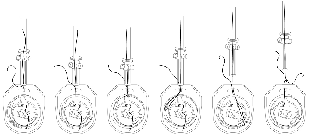
Above, showing the stitching process with top thread and bottom thread in the rotary hook.
Examples of technical embroidery threads:
- Polyester – Standard thread in a wide variety of colors and lusters
- Nomex – High temperature thread with self-extinguishing properties
- Kevlar – Strong thread resisting cutting, flames, and heat
- PTFE – High chemical resistance and very high heat tolerance
- PEEK – Resistant to extreme environments and chemicals
- Nylon – Melts under heat, used often in composites
- Dyneema – Extremely strong, low-weight high tenacity thread
- Cotton – Biodegradable and strengthens when wet
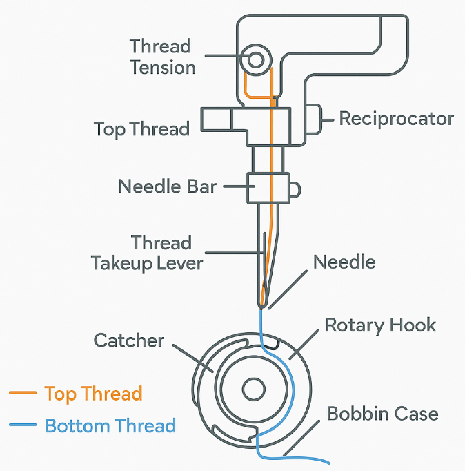
Key terms and diagram of the stitching assembly and threads.
Thread Tension Systems
Top Thread Tension
- Controlled by tension discs, springs, and pre-tensioners
- If too tight: fabric puckering, thread breakage
- If too loose: loops form on the fabric surface, inconsistent stitching
Bottom Thread Tension
- Set using a small adjustment screw on the bobbin case
- Must balance with the top tension for proper lockstitch formation
- Inconsistent bottom tension causes nests or loops underneath
Attachments for Stitching Heads
- Cording devices: Feed cords or yarns into the stitch
- Sequin and bead devices: Place decorative elements automatically
- Boring tools: Create decorative stitched holes
- Laser cutters: Inline cutting or etching of fabric
- Zigzag devices: Create width variation in stitches
- 3D puff guides: Help embroider raised effects over foam
-
Upload your completed .AI (preferred) or .DXF files here. If you do not have this software or expertise, our design team can help coach you through the process. In that case, please send any drawings, sketches, or diagrams to begin the process as well as your contact information and we will get in touch with you.